Sunday, May 15, 2016

TAT-2016 Post 36 - Sunday 15 May 2016

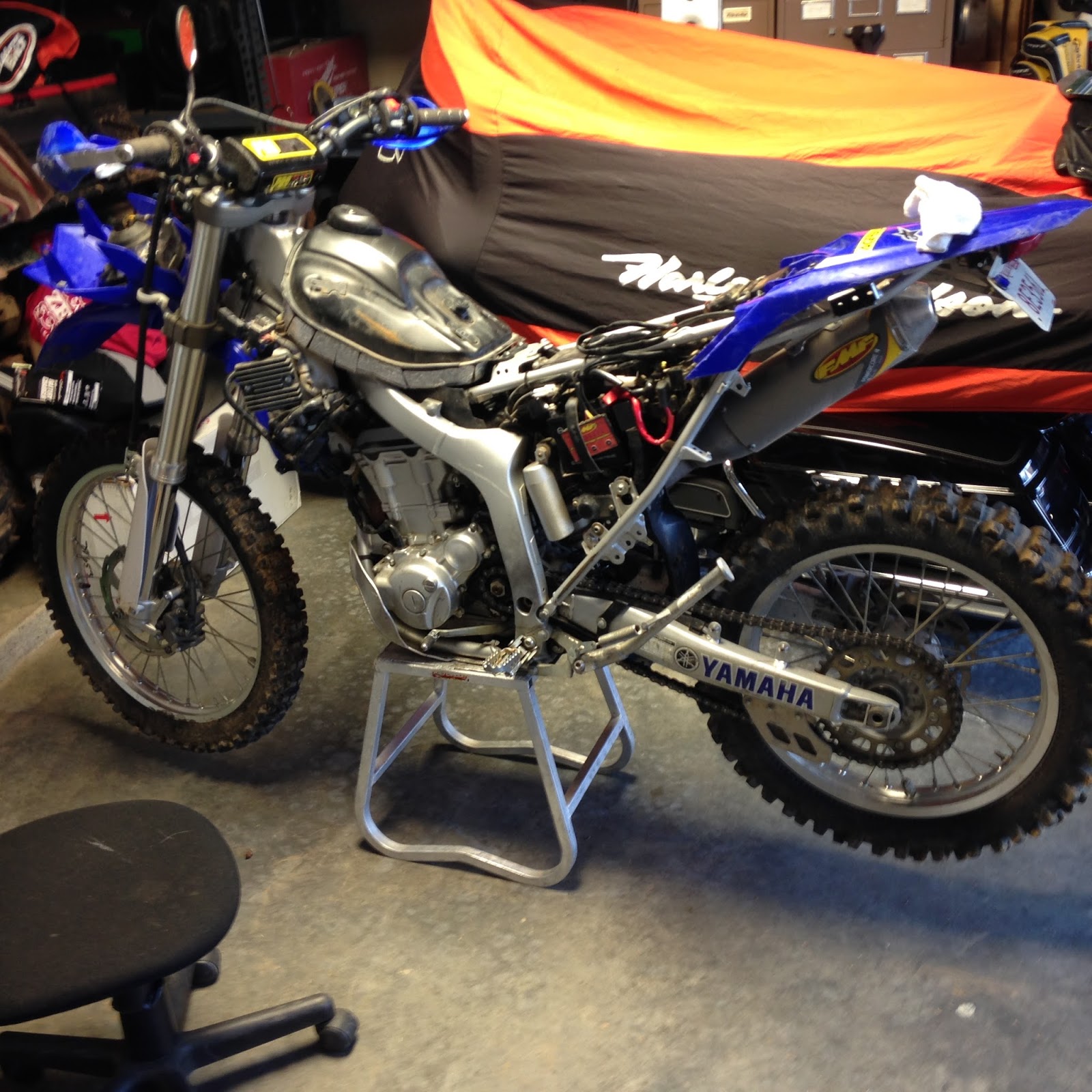
This post is long and probably will be of interest to only those with CRF250Ls since it goes into detail on installing the FMF exhaust system on this bike.

As I stated in my last post (35) I planned on installing an upgrade to my exhaust system this weekend then report on the results after our Memorial Day TAT ride. Sorry but I couldn’t wait to report that this mod is FANTASTIC! I must make the appropriate disclaimer so I don’t offend anyone. All comments below are my impression only and not base on scientific fact.

My 2015 Honda CRF250L is a great bike but stock it isn’t any fire breathing dragon. In fact my first impression riding the bike away from the dealer last Oct 2015 was it is underpowered and definitely did not impress me with its acceleration or even top end speed.

Since then I added the 13t front sprocket, which greatly improved its climbing ability while decreasing the top speed a bit more. Still that was a good mod because it put the 2nd gear exactly in the correct power range to climb most inclines at 18 mph. 1st gear is for only real steep climbs because it is so low the RPM is too high and speed too low for being very useful at any other time.

Leg-1 of our TAT adventure (East coast to AR March 2016) proved my comments above about the 13t mod. Only real issue I had with the CRF on Leg-1 was top speed limitation. I could do 55 mph comfortably and even get to 65 mph if required but the bike was laboring.

I watched numerous YouTube videos on the exhaust upgrade and finally caved in and ordered the complete kit from CRFs Only last week. At $755 this is an expensive modification so I wasn’t real sure if it would be worth the cost but now I can report that it definitely is. I’m sure you could probably get the components a bit cheaper if you shop around or buy them separately but I wanted to make sure they were a matched set so got them all from the same source; CRFs Only.

The kit includes an FMF Q4 Hex Muffler with Megabomb Header plus the EJK Electronic Fuel Control Monitor. The 13t sprocket is an option with the kit but since I had already installed one, this was not required.


The EJK module was delivered separately via USPS and the rest of the kit came via FedEx the following day. As a result, I was concerned that the EJK module had not been preset for the CRF250L so I sent an email to CRFs Only and received an immediate response that it was preset as required. As a side note the customer service at CRFs Only is excellent and I highly recommend them, if you have any kind of CRF.
I couldn’t wait for the weekend to make the modification so I did the complete install on Thursday night.

EJK Electronic Fuel Control Monitor - I began the mod by installing the EJK module under the seat using the supplied Velcro pad. It goes in the area originally reserved for the owner’s manual. Next I removed all the plastic panels on both sides for easy access and visibility plus the seat. The EJK has one long cable with two connectors that go in-line with the CRF harness connector on the fuel injector. The EJK also has a separate ground wire that can go direct to the negative battery terminal or to the common ground bolt on the right side by the fuel tank; I selected the ground bolt. I ran the cable on the left side to just under the fuel tank in the general area for the throttle valve and injector. As much as I tried I could not get my hand or any tool into disconnect the connector on top of the fuel injector. I finally removed the two front bolts and single long rear bolt that attach the fuel tank to the frame. I could then lift up the fuel tank and the throttle valve and injector connector were easily reached. I disconnected the injector connector and replaced it with one of the connectors on the EJK cable and then put the original injector connector into the second connector on the EJK cable. As simple as that. While I had access to this area I put plenty of tie wraps on all of the wire to ensure they would not vibrate against something and possibly wear through the protective cover. I then replaced the fuel tank bolts and finished tie wrapping the cable and ground wires to the frame.

Because I had not started on the exhaust mod yet I started the engine just to see if the EJK would let the engine operate normally which it did. I didn’t want to get the system hot so I shut it down after a short few seconds. I had briefly read the instructions when I opened the box for the muffler and saw that I needed Hi-Temperature Silicon to seal the new FMF exhaust system. I went to Auto-Zone and found just what I needed and returned to start the rest of the modification.

FMF Muffler and Megabomb Header - I removed the old exhaust system including the header pipe in less than 10 minutes. I also removed the heat shield from the old muffler to be reused on the FMF. I had watched a great YouTube on how to do this mod so was pretty familiar with what I needed to accomplish; at least I though I was. This is when I realized just how heavy the original muffler on the CRF really is. It feels like a boat anchor compared to the new FMF muffler. Plus the FMF header pipe is significantly larger in diameter compared to the original header pipe. A lot more air can go through the FMF system for sure.

This is where things didn’t go as smooth. In my haste to get the mod completed and my over confidence I immediately added the red Hi-temp Silicon to the header pipe going into the cylinder head and put it in place. I hand tightened the two nuts holding the header to the cylinder then noticed that the end of the header pipe was on the outside of the frame rather than on the inside where it belonged. I had to undo the two nuts and pull the header out of the cylinder in order to get it inside the frame. Red silicon was getting everywhere and I wasn’t sure I would get a good seal so I removed the header, cleaned off the silicon and started over. The silicon is not easy to remove once applied so have plenty of rags.

Once I had the header installed correctly with the two nuts loosely holding it to the cylinder head, I then put red silicon on the inside of the muffler pipe that slips onto the end of the header pipe. When I tried to slip the muffler onto the end of the header pipe I then realized they were the same diameter and there was no way one would slip over the other! Now I’m really getting irritated. I cleaned off the red silicon from the muffler pipe and tried to figure out why they would be the same diameter since the kit did not come with any type of sleeve or clamp to hold the two together. I decided I needed to read the instructions more thoroughly.

When I unpacked the muffler components there was lots of packing paper in the boxes, which I had just piled in a corner of my garage. I could not find the instructions in this mess. I looked everywhere until I realized I had taken them into the house to read just before I went to get the red silicon; what an idiot. I re-read the instructions slowly and that’s when I saw the comment about removing the sleeve in the muffler if you are also installing the FMF header. As I stated, the original header pipe is smaller than the new FMF header pipe therefore the reason for the sleeve. I used vice-grips to pull out the sleeve, which was not an easy task, then went back to the installation effort.

I once again added red silicon to the inside of the muffler pipe and then slipped it onto the end of the FMF header pipe. These two units are a tight fit so they don’t have to use a clamp to seal the connection so it takes a bit of effort to get them in the right position to match the mounting holds for the muffler bolts.

This is where I need to explain that only part of the original heat shield is reused on the FMF muffler; the white portion. The kit comes with an adapter plate but until I re-read the instructions, I could not figure out how to get the white heat shield, the adapter plate and the FMF muffler into a complete unit. It works but it isn’t obvious. Now the problem was getting the back muffler mounting bolt installed and tighten the whole system up. I used a box end wrench to hold the nut on the back of the muffler and then found that I couldn’t get the wrench off the nut when it was tightened due to it being against the heat shield; crap. I had to loosen everything again and pry out the wrench. I then used an open end wrench and that worked.

The complete kit took me 3 hours to install but if you read this blog and learn the correct way to do the install it could be done in an hour or two max. The kit quality is excellent but the instructions leave lots to figure out on your own. The red silicon instructions said to wait a minimum of 12 hours before starting the engine to let the silicon set. I decided to wait till the next morning to hear how the CRF sounded with its new exhaust system.
BTW I had also planned on doing an air box mod at the same time but I only removed the rubber snorkel out of the top of the air box. That did provide a bit more room for air to get to the engine and I may wait a while before doing more mods in this area.

12 hours later – I got up to go to work the next morning and immediately went to the garage to start the CRF. What a difference in sound. It was definitely louder, especially in an enclosed garage. I felt for exhaust leaks and found none but one thing I did notice as I walked behind the CRF was the strong jet of exhaust gas coming out of the muffler. I never noticed that on the stock muffler so there is definitely a lot more airflow with the FMF.

I was anxious to see how it impacted the performance of the bike so decided to ride the CRF the 12 miles to work on back 2-lane paved roads through some open county farmland.

Performance Review – This review is based on the ride to work and back on Friday and a 50 mile ride I took today on mostly 2 lane paved roads plus a short run on some dirt and gravel roads and trails.

This mod made the CRF250L into a new bike. I can’t start to express the difference in performance but here are few of the highlights:

1 – Acceleration is eye opening. The front end actually feels light and I’m sure I could do a wheelie if I only tried. One interesting thing is that the engine seems to rev much quicker to red line; no tachometer so only going by sound. In fact I never remember reaching a point that the engine felt like it was revving too much with the stock muffler but I do with the FMF. Since 1st gear is pretty low, you shift to 2nd within seconds but there is plenty of power to just keep going through the gears.
2 – Top speed is much higher. On my way to work I reached 70 mph and still had throttle I could use but the bike was feeling squirrely with the knobbies so I didn’t try for max top speed. It definitely has more power at the top end. I could cruise at 60-65 and the engine felt like it was not working hard at all. Even had acceleration if needed to pass even while doing 65 mph.
3 – Sound. The bike sounds tough now compared to the Vespa motor scooter sound the stock CRF made. It is much louder and if you really get on it from a dead stop it can really sound loud. This was something I was concerned about for several reasons including I live in a neighborhood that doesn’t see a lot of loud cars/motorcycles. I quickly realized that as long as I don’t open the throttle wide open I can keep the overall sound down to a reasonable level while in residential and business areas. I still like it though. It didn’t seem to be so loud during normal riding that it would be annoying. Maybe for someone following me but who cares about them, they’re eating my dust anyway.
4 – Street Legal? This is an interesting question. The FMF web site and the paperwork that comes with the FMF components make it clear that these units are NOT street legal, especially in California. I assume because it eliminates the catalytic converter that it no longer meets the federal environmental rules. Something that anyone installing this mod must be willing to accept.

Summary – I already loved the CRF250L but this mod made a VW Bug into a sports car and I like it a bunch. Woodrow doesn’t have this mod so it will be interesting to compare the two CRFs on the Memorial Day TAT ride.


Wednesday, May 11, 2016

TAT-2016 Post 35 - Wednesday 11 May 2016


Planning progresses for leg-2 (AR to CO) of our TAT adventure scheduled for early August 2016. A number of events have happened or will happen in the near future that are worth mentioning.

1 - Our new member, Jeff, who is also my oldest son has been hit hard with the adventure bug and is in full upgrade mode on his recently purchased 2008 Yamaha WR250R. This past week-end I drove to Tulsa area from Little Rock to celebrate my mom’s 90th birthday and Mother’s day but also to go riding dual-sports with Jeff. I arrived around 5:30 pm Friday at Jeff’s house just in time to find him putting a new battery into the WR. His story was that he had just re-installed the turn direction lights that had been removed by the previous owner but when he tried to start the bike, all it did was click continually; typical bad battery indication or bad ground connection. The bike had been running fine until he started the turn light work.

The new battery was filled with acid, charged and installed into the WR in short order. When the ignition switch was turned on, the tail light was flickering and when the ignition switch turned to start, it again only clicked continually. The horn wouldn’t work nor any other electrical component. Our first thought was there must be a short somewhere because if we moved the cable harness in certain areas the horn would start to work and lights go on steady. We spent hours trying to find a bad connection or shorted wire. It was almost 9 pm and the bike was torn all apart with the cable harness hanging loose in most places and the bike would still not keep the power on reliably. We finally figured it had to be a bad battery, even though it was new. Jeff took the battery out and went back to the auto-parts store just before they closed for a replacement. When they tested the battery, sure enough it had a bad cell!!


Jeff returned home with the new new battery, added acid, charged it for an hour and reinstalled into the WR. By this time it was close to 11 pm. When he turned on the ignition, all the lights were on steady, the horn worked and we were getting excited. He tried to start the bike, the starter turned but the bike would not start or even attempt to start. After server tries there was definitely a smell of fuel from flooding the system but no indication that the sparkplug was even getting any power. We finally gave up and went to bed. Note: The fuel smell was curious. I didn’t think a fuel injected bike would flood but evidently this one will. A review of the owner’s manual even states to open the throttle full to clear out the engine if it has trouble starting.

The next morning we started again. I had the bike schematic in my lap while Jeff attempted to find out why the ignition wasn’t getting any power. About this time we read in the manual how the diagnostics tool worked using codes shown on the instrument cluster. I know, we should have done this early last night but we were both unfamiliar with the WR’s capability. We ran through the test, got an error code, I looked in the manual what it meant and BINGO, problem identified! It was the lean angle sensor. When Jeff was moving all the harness and components around last night looking for a shorted wire he pulled several of the sensors out of their mounting clips, including this one. What he didn’t know was that this sensor must be positioned correctly or it will shut off the ignition on the bike. We found the sensor and installed it into its correct mounting spot and like magic the bike started immediately. It was 9 am Saturday. Although Jeff was pretty irritated I told him that this was all good experience. We now know where all the sensors are located and how to use the WR diagnostics to troubleshoot these types of problems. It could be invaluable on the trail in Utah or some other isolated spot on the TAT. We finally got to ride some local back roads and even a few single tracks and it looks like his WR will do the job.

2 – Woodrow’s leg is healed, at least that’s what the doctor tells him. This is the same doctor that didn’t recognize that it was broken in the first place. Woodrow says it’s fine and not hurting and that he’s ready to ride again. More on that later.

3 – Terry just bought a new KTM-690 to replace his KLR650.  The KTM is around 300 lbs. compared to the 400+ lbs. of the KLR. Terry is a big guy but he quickly realized during Leg-1 that a heavy bike is lots of work when riding bad roads and water crossings. Steve made this same discovery prior to starting Leg-1 and that is why he also replaced his KLR650 with a WR250R. Don’t get me wrong, larger bikes are great, especially if there are lots of highway miles to cover. In addition, these smaller bikes may suffer out west when we hit the high passes but lots of TAT riders have been successful on smaller bikes and the one thing I see written over and over again is lighter is better on the TAT. Our experience from Charleston, SC to Little Rock, AR is that a 250 is perfect. Only time will tell if that holds true for Legs 2 and 3.


4 – I continue to throw more money into mods for my CRF250L. I really love this bike. It is so much fun to ride. After riding Jeff’s 2008 WR250R this past weekend the CRF also rides smoother and is easier to shift than the WR. It also handled all the gear plus me on Leg-1. My CRF is a 2015 model with 3800 miles (1431 miles during TAT Leg-1) since Oct 2015 when I bought it new. Jeff’s WR250R is a 2008 with about 4500 miles.

The latest modification to my CRF is arriving this week; an FMF Q4 Hex Muffler with Megabomb Header plus the EJK Electronic Fuel Control Monitor. This is a very popular modification to the CRF and adds around 3 horse power to a pretty tame motorcycle. All the YouTube videos on this mod were very positive and I’m anxious to get it installed this weekend. In addition to adding these components, I will also do an AirBox mod that gets more air into the engine. This will be limited to adding a larger diameter snorkel tube to the top and maybe removing the metal screen in front of the air filter. My experience on Leg-1 after dumping my CRF during a water crossing is that I want to keep the AirBox water proofing in place and only make the input hole at the top larger. If water gets that high on the bike, it won’t matter how large the hole is. The FMF muffler is about half the weight of the stock muffler; 12 lbs compared to about 6 lbs. I also have already installed the 13 tooth (13t) sprocket shown in the picture below that replaced the original 14t.


One other addition I plan on trying is a different mounting plate for my RotoPax Fuel tank. On Leg-1 I had the RotoPax mounted flat on my rear rack. This made me have to have my GL bag on top of the RotoPax on the back and my rain gear bag in front under the GL bag. It worked OK but I would like to get my GL bag lower and have it setting on my seat and directly onto the rear rack. You’ll see this in pictures I will take after I try out the new mount this weekend. The metal plate weighs almost 5 lbs so I hate to add that extra weight and unless it makes a significant improvement in my gear arrangement, it won’t be used.

5 – I had mentioned in a previous post that we were going to try and do the rest of AR and some of OK TAT sections (334 miles total) in the next few weeks so as to shorten the August Leg-2 to Colorado. We have already ridden all of the AR TAT from the east state border to just north of Dover, AR.  That leaves about 170 miles of AR TAT from Dover to the OK/AR state line. Our plan for a Memorial Day TAT ride is to finish all of the AR TAT.

Saturday morning we will all arrive at Dover, AR around sunrise to unload the bikes and gear up for the ride. Right now it will be:

Mike on his CRF250L with new FMF exhaust system installed
Jeff on his WR250L
Woodrow on his CRF250L
Terry on his new KTM-690
Steve on his WR250R won’t be going since he has other commitments

We connect with the TAT about 10 miles north of Dover where we ended a previous TAT ride several months ago (red Flag on right side of map).


We will head west on the TAT through the Ozark National Forest through some very scenic areas of the state. We will ride till close to sundown and stop for the night in a local motel. If the roads are good and water crossings no issue we should be able to reach the OK border; 169 miles. If we don’t make the OK border we will stop short and finish up on Sunday morning (Red Flag on left side of map above). The mileage chart for this TAT section is provided below:


At the OK border we will ride 2-lane secondary paved roads 121 miles back to Dover where our trucks will be parked.


That’s all I have to report this time. Next post I will have a trip report of our ride described above and a review of the FMF exhaust mod to my CRF250L. In addition, I’ll report how Jeff handles setting on a dual-sport seat for 2 days. He’s used to riding on big Harley Davidson comfort seats.


Sunday, May 1, 2016

TAT-2016 Post 34 - Sunday 1 May 2016


New significant detail since last post, at least for me. My oldest son has decided he couldn’t let his dad have all the fun so has committed to go with us on Leg-2 and maybe Leg-3 of our TAT adventure. Jeff is a long time motorcycle and ATV rider plus an excellent mechanic so will be a welcome addition to our group. I have been trying for years to get him to join me on my adventures so really looking forward to having a great time with him. I actually sold Jeff my Harley Davidson after my AK1 Alaska attempt when I bought the Yamaha Super Tenere for AK2. He has decided to come to the dark side, dual-sport rider, and recently bought a used Yamaha WR250R for the TAT ride. It is pretty complete and only needs a rear rack and a few extras to be TAT ready. I plan on taking my CRF to Tulsa this coming weekend where he lives to ride some trails with him. The real reason for the trip is my mother’s 90th birthday but the dual-sport ride is a welcome addition.


We always expected that a few more riders might join us on the next Leg to Colorado. As we get firm commitments I will add them to the blog. I’m even working with a retired friend to be a support vehicle who would carry most of our gear so we can ride extra lite. He hasn’t committed yet but there is still time to convince him before we launch in August.

Woodrow is still on crutches, some of the time, trying to heal his broken leg so he can get some more practice before Leg-2. If you remember we had another friend mess up his wrist on a practice ride and still has a cast on it for a few more weeks. Interesting that I’m at least 20 to 30 years older than all the other riders and I haven’t gotten even a scratch on any of our rides plus Leg-1 of the TAT. These young guys just can’t keep up with the silverbacks.

Last post I mentioned I was mounting a tool tube on my CRF and initially thought about installing it on the front of the skid plate. After several comments from experienced riders who told me their experiences I elected to move it to the left side of the bike. It’s not pretty but it fits nicely and keeps it out of the mud. I removed the stock toolbox and helmet lock to make room for the bracket. I took a short ride today and it is completely out of the way and looks like it will work as planned.


I weighed my tools and found that they were 10.2 lbs, plus it was hard getting them all in the tube. As a result, it made me reevaluate my tool list. I replaced some of the heavy wrenches with stubby wrenches, replaced a heavy axel wrench with a lighter one and cut the handle off a favorite tire iron to make it less bulky. Result is my tools now weigh 8.6 lbs and fit perfectly in the tube. One thing I didn’t consider was how to get the tools out of the tube when it is mounted on the bike. I considered putting then in a nylon bag with a cord to the top of the tube, too much of a problem. I even considered putting in one of those grabber things that has the four wires that extend with a button at the other end, too complicated. I finally realized that I could remove the tube by releasing the four straps with a screwdriver in less than a minute. I will just put my multi-function screwdriver at the top of the tools in the tube to make this possible.

Lastly, I’ve included a couple of pictures of a pad I picked up at a motorcycle shop they use under the kickstand of bikes on the showroom floor. I added a length of cord for my purpose. On Leg-1 I dropped my bike a couple of times while parking on less than firm ground. The CRF is significantly top heavy when fully loaded, which didn’t help. When I know I have to park on soft ground I drop the pad to the ground first and tie the cord to the handlebars. I can kick the pad under my kickstand to increase its footprint. After remounting I can retrieve the pad while on my bike, wrap the cord around the pad and store it in the pocket on the back of my tank bag. I’m sure I’m not the first to think of this but I’ve never seen it described before so here it is.


BTW, Jeff has sent me several texts today asking what he needs in bike mods and riding gear for the TAT Leg-2. I’ve created another monster and I’m sure his wife, my daughter-in-law, has used my name in vane recently.

That’s all for now, until next time. Ride safe.